Step Wiring for Motor


diplonics
Newbie
Avatar
Gender:
Location: Longford
Age: 50
Posts: 15
Registered: 11 / 2018
My Motorhome: Mizar 190
Base Vehicle: Fiat Ducato 1999 2.8TDI
Subject:

Step Wiring for Motor

 · 
Posted: 17.03.2022  ·  #1
I have 99 Ducato Mizar 190.
About 3 years ago the retractable step stopped working.
Stripped lots of stuff and eventually discovered the motor bushings had collapsed.
Got the motor reconditioned and sat it on the workbench to fit later.....3 years later!!!
Anyway, put it back together today and no joy on it working so any hints on what to check further would help.

What I know is as follows.
If I connect the reconditioned motor to a 12v battery, it works forward and reverse, as it should.
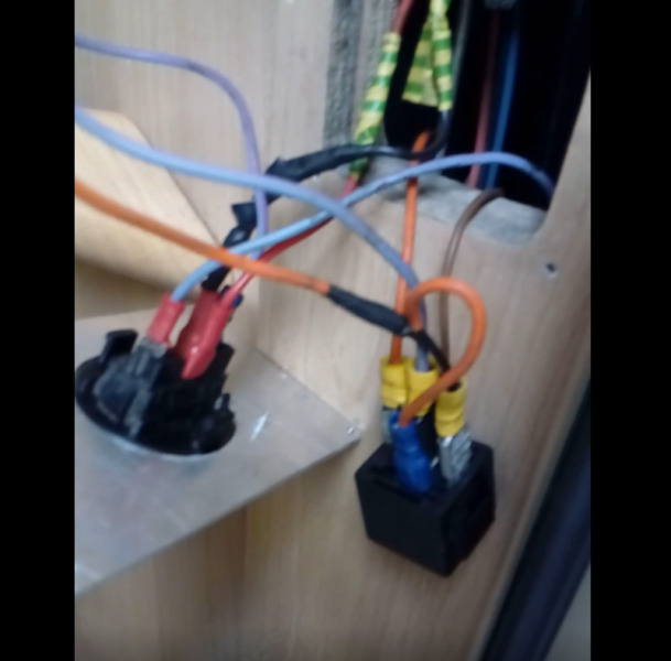
There's an orange and purple wire in the control housing under the camper behind the step where the motor goes.
If I connect a multimeter to these wires I can see +14(ish)v when I press the step button one way and -14(ish)v when pressed the other way.
But when I add the motor into the circuit nothing happens at all, motor doesn't move and voltage reads 0.
I've also added a new relay to the circuit as in image but not sure it that makes any difference as doubt the old one was broken anyway.....


ntg
Eat's Sleep's craic
Avatar
Gender:
Location: Portglenone. Co Antrim
Age: 24
Posts: 3822
Registered: 04 / 2012
My Motorhome: Autotrail
Base Vehicle: Comanche
Subject:

Re: Step Wiring for Motor

 · 
Posted: 17.03.2022  ·  #2
If the live is showing 14v it most likely is an earth problem.

Liked by: eirebus

Ally
Founder
Avatar
Gender:
Location: Muckamore, Antrim
Age: 55
Homepage: motorhomecraic.com
Posts: 32600
Registered: 08 / 2011
My Motorhome: Lunar Roadstar 780
Base Vehicle: Fiat 2.8 JTD
Subject:

Re: Step Wiring for Motor

 · 
Posted: 17.03.2022  ·  #3
@JJF is the man

Liked by: ntg

JJF
Eat's Sleep's craic
Avatar
Gender: n/a
Location: Donegal
Age: 56
Homepage: MotorhomeCraic.com
Posts: 5319
Registered: 10 / 2014
My Motorhome:
Base Vehicle:
Subject:

Re: Step Wiring for Motor

 · 
Posted: 17.03.2022  ·  #4
You need to measure the ‘current’… you can get +/- 12v but the current could be minimal.
As Norman says, can be a grounding problem too, but the circuit is designed to supply the + & the - for reverse polarity.
The switch obviously is giving you the reverse polarity to rotate the motor clockwise/counterclockwise but the resistance may be high.
**tip** test the circuit using a 70/55 w headlight bulb, this will give you over 10a draw.
If stuck I can send you a schematic for a new circuit.

Liked by: eirebus, Ron W, sprinter

diplonics
Newbie
Avatar
Gender:
Location: Longford
Age: 50
Posts: 15
Registered: 11 / 2018
My Motorhome: Mizar 190
Base Vehicle: Fiat Ducato 1999 2.8TDI
Subject:

Re: Step Wiring for Motor

 · 
Posted: 29.03.2022  ·  #5
Apologies for delayed response, was away on hols, unfortunately without campervan as its rear brakes are being rebuilt!!!
Anyway, thanks a mill for input here.
I tried the bulb (12v/55w) thing and no joy, it didn't light up.
Yet the multimeter is still showing +-13(ish) voltage when I press the switch.
So probably a wiring problem, bet I fiddled something into the wrong place when I was originally dismantling the whole thing trying to find the problem.
Anyway the step has no obvious manufacture markings but looks same as a Thule version with this wiring layout, https://www.thule.com/-/s/appr…446269.pdf
Page 9 wiring for auto retraction..
If you guys reckon I should be using a different wiring then please send my way, it would be appreciated.
So probably continuity test all the wires and basically start from scratch.

Other source of issue possibly the ground as I got the underbody cleaned and schutz'd about 3 years ago but can't remember if the step failed in and or around when it was done, maybe!!!

Thanks again,

Paul


MickyMac
Love's the Craic
Avatar
Gender:
Location: Kildare
Age: 53
Posts: 101
Registered: 03 / 2013
My Motorhome: Giottiline T38
Base Vehicle: Ducato
Subject:

Re: Step Wiring for Motor

 · 
Posted: 29.03.2022  ·  #6
diplonics
Newbie
Avatar
Gender:
Location: Longford
Age: 50
Posts: 15
Registered: 11 / 2018
My Motorhome: Mizar 190
Base Vehicle: Fiat Ducato 1999 2.8TDI
Subject:

Re: Step Wiring for Motor

 · 
Posted: 29.03.2022  ·  #7
The video was certainly helpful but didn't sort issue.....yet!
Following the video I did have a couple of wires incorrect but even correcting them didn't fix issue.

So, the only difference between the video wiring and mine is the brown goes from the step to the relay instead of the grey.
While the grey is earthed to the bodywork instead of going back to the neutral on the switch.
I'm presuming this is fine as both wires just create a circuit to a switch in motor box that detects when the step is up.

The only other bit not in my circuit is the diode or the buzzer shown from 3:30 on.
Probably not needed and only extra warning bits?

Anyway, when I connect a multimeter set at 20V to the circuits purple and orange wires I still get the +/-13 when I press the switch.
But when I connect a 55w bulb to the same wires and use the multimeter to test when the switch is pressed I get nothing.

I haven't checked continuity on every wire but I have tested both my old and new relay with same result.

Any other helpful diagnosis tips welcome!!
Thanks as usual..


sprinter
Eat's Sleep's craic
Avatar
Gender:
Location: Co Wicklow
Age: 93
Posts: 7431
Registered: 01 / 2015
My Motorhome: Matilda 2 Pilote 703FP Explorateur
Base Vehicle: 3ltr 318 Sprinter Automatic
Subject:

Step Wiring for Motor

 · 
Posted: 29.03.2022  ·  #8
When most 12v doesn't work, first check + then - sounds like you can prove + but you haven't yet proved -,
Go back to the bulb and if it means getting a long length of cable all the way back to the battery, prove you have a complete circuit, then connect this to your step earth.?


diplonics
Newbie
Avatar
Gender:
Location: Longford
Age: 50
Posts: 15
Registered: 11 / 2018
My Motorhome: Mizar 190
Base Vehicle: Fiat Ducato 1999 2.8TDI
Subject:

Re: Step Wiring for Motor

 · 
Posted: 17.04.2022  ·  #9
Fixed....it was the purple wire running from the step motor to the switch....
So thanks guys for the advice, the video was perfect to step me through what wire does what and the simple idea of a bulb and checking for a + to - circuit was how I found the issue.
Taking the switch and relay out of the loop I could get a circuit from + to either the battery - or step bodywork - on all wires except the purple.
Once I pulled the purple wire out I spotted a lump half way along it, which was hidden in the bodywork.
Bending the wire at the lump and it just split open and a greenish/white powder came out...so I'm assuming age/wear-and-tear caused a break in the plastic coating and the wire inside got wet/hot and disintegrated....
Anyway, replaced the wire, put all back together and its now working again after 2 and a half years...the bungy cords can go back in the garage!!!

Thanks again guys.

Paul


diplonics
Newbie
Avatar
Gender:
Location: Longford
Age: 50
Posts: 15
Registered: 11 / 2018
My Motorhome: Mizar 190
Base Vehicle: Fiat Ducato 1999 2.8TDI
Subject:

Re: Step Wiring for Motor

 · 
Posted: 23.05.2022  ·  #10
HI Guys,
Step is broken again...so 1 quick question if someone knows...
In the wiring video at 3:32 there's a diode fitted.
I don't have this in my circuit.
What could the consequences of this be?
I also don't have the buzzer in my circuit but assume that's fine not being there?

Bit of further reading in Thule Manual says:
'Put the electrolytic capacitor 2200 microFarad 16 VDC onto the relay coil. This capacitor makes the step retract further after the current has been disconnected by the Thule Step switch. In this way, the step is retracted until its endstop.'

Anyway, step worked fine for couple days, then parked it up for a week and when I took it back out no working step!!
Ended up pulling out the motor again and upon internal inspection a wire was broken.
It was a reconditioned motor with new brushes, the wires from the brushes go into some sort of electronic unit, resistor or something, and the solder on one of the wires had come off.
The electronic unit looks like it overheated and maybe melted the solder!!!

Probably going to buy a new motor and fit the diode but just a quick ask if the missing diode could be causing a voltage spike that caused the motor problem??

I don't remember there're being a diode in the circuit when I first dismantled it, but that was 18 months ago at this stage..

Thanks again,

Paul


diplonics
Newbie
Avatar
Gender:
Location: Longford
Age: 50
Posts: 15
Registered: 11 / 2018
My Motorhome: Mizar 190
Base Vehicle: Fiat Ducato 1999 2.8TDI
Subject:

Re: Step Wiring for Motor

 · 
Posted: 29.03.2023  ·  #11
Just for the technical record on this post and to finish it out.
The step motor has been working fine, touch wood it doesn't pop tonight!!!, for almost a year now.
I did end up getting a new motor, not much more cost wise than the cost of a 2nd recondition of the old, which I reckon got burnt out a second time.
Anyway, I rewired the whole system to include the capacitor/diode and an indication light, both of which were missing from the original circuit.
First thing that showed up was when the step was retracted from a engine start that the light didn't go off.
So I reckon this was the cause of the most recent problem of motor burnout.
Basically the problem was that step was not retracting enough to push the 'fully retracted' switch.
Years of step strain meant it didn't quite touch the switch properly and without the warning light it was hard to track.
Anyway, sorted the step strain issues and it now retracts properly, hits the switch and the light goes off!!!

Liked by: eirebus, Galldar

Selected quotes for multi-quoting:   0

Registered users in this topic

Currently no registered users in this section

The statistic shows who was online during the last 5 minutes. Updated every 90 seconds.